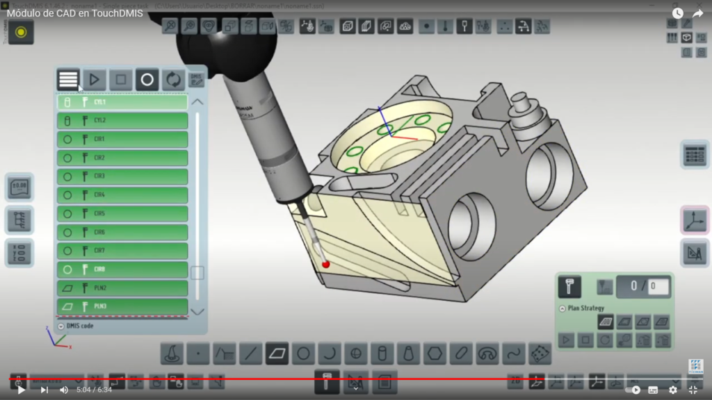
He CAD module in TouchDMIS helps to optimize work times. It also enables the measurement of more types of surfaces in a comfortable and simple way.
In this video you can see the differences between using this module and not using it through real practices.
5 Differences between measuring with or without the CAD module in TouchDMIS
Below is a brief summary of the measurement procedure described in the video:
Define a plane
Thanks to this CAD module Defining a plane is much simpler. Just click on the plan and automatically calculate the elements that define it: the center and the vector. This way we get a plane in its maximum size for that piece.
However, to measure any element without this module, for example a plane, we need to define the nominal value of the element so that the plane is the center and the vector. To do this, we must look at those coordinates in the manufacturing plan and calculate them.
Once generated, we get the points automatically and can change them manually. Although the program places them automatically without knowing if there will be material or a hole at the measurement point. We can move them by hand but we have to check those coordinates with the manufacturing plan manually.
Selection of points to palpate
Having the CAD we can select the plane where we want to place the probing points, for example if we enter a large number automatically, places them where there is material; avoiding holes.
However, without the module, the plane (the center and the vector) must be defined first. Once the plane has been created, the number of points to be measured must be indicated, but in this case they are not distributed evenly. Furthermore, it does not take into account whether there is material or not.
Implementation of the program without a real piece
You can create the measurement program from the CAD of the part, without the need to use the three-dimensional measuring machine to define the probing points. That is, The machine may be used to measure other parts and in parallel create the program even before creating the part.
Avoid collisions
From the CAD file you can define the routes to measure the different elements. Visualizing where the palpation will go to avoid any type of collision. If we see that there is going to be a collision, we just have to modify the trajectory. We do this by modifying the safety distance.
If we do not have the module, we only see the possible path but not whether it will go through the piece. Therefore, we do not detect possible collisions.
More visual measurement reports
Measurement reports with CAD module They are much more graphic and more visual..
5 Advantages of the CAD module in TouchDMIS
- Speed when programming: This is possible because the theoretical dimensions are taken directly from the CAD, without the need to enter them manually from the 2D plan. In addition, the software automatically calculates which points to take, giving the option of modifying them and launching the machine to measure autonomously. Another reason for the greater programming speed is the specific functions to facilitate the programming of measurements in crowns or matrices of elements.
- Measurement on curved surfaces, which would otherwise be impossible to produce, such as car bodywork or elastic parts.
- Measurement without physical part: There is the option of generating the entire measurement, including the probing strategy and the air-borne passage points, without the need to have the physical part. Thus avoiding all types of collisions that could be harmful to the device.
- More visual graphical reports, where the measured elements, with their tolerances and deviations, are indicated directly on the CAD of the part.
- Software also suitable for viewing: no need to purchase any other specific software.
For more information on TouchDMIS software or our measurement capabilities, please see our Web and channel of YouTube.